PCB Routing Machines: Insights Into Circuit Board Routing, Precision and Manufacturing Applications
PCB routing machines are computer-controlled systems used to cut, shape, separate, or machine printed circuit boards and related materials.
Unlike PCB electrical routing, which refers to designing conductive traces between electronic components, a PCB routing machine physically removes material from a circuit board using a rotating cutting tool. These machines are used in electronics manufacturing, prototyping, board modification, depanelization, and specialized circuit-board production where controlled mechanical machining is required.
Context
What Are PCB Routing Machines?
A PCB routing machine is a mechanical machining system designed to follow programmed paths across a printed circuit board. The machine normally uses a high-speed spindle, cutting tool, workholding arrangement, motion-control system, and computer software to guide the cutting process.
The machine can create openings, remove unwanted board material, cut board outlines, or separate individual circuit boards from a larger panel. Depending on the configuration, it can work with materials such as FR-4, composite laminates, aluminum-backed boards, and other PCB substrates.
The term "routing" can sometimes create confusion. In electronic design, PCB routing means arranging conductive traces between components. In this context, routing refers to physical machining performed by a cutting tool.
How PCB Routing Machines Work
A typical process begins with a digital board design or machining file. The required cutting paths are converted into machine instructions that control the movement of the spindle and cutting tool.
A basic sequence includes:
Preparing the PCB panel or individual board
Loading the machining file
Securing the board on the worktable
Selecting an appropriate routing tool
Setting spindle speed and feed parameters
Establishing the machine reference position
Running the programmed cutting path
Inspecting the machined board
The exact sequence depends on the machine type, board material, cutting geometry, and production requirements.
Main Components
Several components work together to control the routing process. The spindle rotates the cutting tool at a controlled speed. Linear motion systems move the tool along programmed X, Y, and sometimes Z axes.
A workholding system keeps the board in the required position during machining. Some systems use vacuum tables, clamps, fixtures, or combinations of these methods.
The control software interprets machining instructions and coordinates movement. Additional systems may include cameras, sensors, dust extraction, automatic tool measurement, and vision-based alignment.
PCB Routing and Depanelization
PCB routing machines are commonly associated with depanelization, which involves separating individual circuit boards from a larger manufacturing panel. Routing can create controlled grooves or paths around board outlines so that individual units can later be separated.
Compared with manual cutting, computer-controlled routing provides a defined cutting path and repeatable movement. However, the appropriate separation method depends on board geometry, material, component placement, production volume, and mechanical requirements.
Importance
Supporting PCB Manufacturing
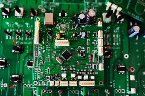
Printed circuit boards contain conductive traces, drilled holes, components, connectors, and other features that must remain within defined dimensions. Physical machining can therefore be an important part of board fabrication and assembly.
PCB routing machines help manufacturers produce controlled board outlines and openings without relying entirely on manual cutting methods. The process can also be integrated with other PCB manufacturing stages.
Precision and Repeatability
Mechanical routing involves several variables, including tool diameter, spindle speed, feed rate, cutting depth, board thickness, and material characteristics. Controlling these parameters helps maintain the intended machining geometry.
Repeatability is particularly relevant when multiple boards are processed from the same design. Variations in fixtures, tool condition, machine calibration, or board material can still affect the result.
Supporting Prototyping
PCB routing machines can also be used during prototype development. Engineers and laboratories may need to modify board outlines, create openings, or produce small quantities of specialized boards.
Computer-controlled machining allows a digital design to be translated into a physical cutting path. Changes can then be incorporated into a new machining file without manually redrawing the complete cutting geometry.
Handling Different Board Designs
PCB assemblies can vary considerably in thickness, dimensions, component density, and material composition. A routing system may therefore need adjustable workholding, tool selection, spindle settings, and cutting parameters.
Some boards also contain sensitive components close to the cutting path. Mechanical vibration, dust, heat, and tool contact must be considered when defining the machining process.
| PCB Routing Factor | Typical Consideration | Effect on Process |
|---|---|---|
| Board material | FR-4, composite, metal-backed board | Influences tool selection |
| Board thickness | Thin or thick substrate | Influences cutting depth |
| Tool diameter | Selected according to geometry | Affects corner radius |
| Spindle speed | Matched to tool and material | Influences cutting behavior |
| Feed rate | Tool movement speed | Influences machining load |
| Cutting depth | Material removal requirement | Affects passes and tool load |
| Workholding | Vacuum, fixture, or clamps | Influences board stability |
| Dust extraction | Material debris management | Supports cleaner operation |
Quality Considerations
After routing, boards can be inspected for dimensional accuracy, edge condition, burrs, cracks, delamination, tool marks, and unintended damage. Inspection requirements depend on the board design and manufacturing specification.
For electronic assemblies, it may also be necessary to verify that routing has not damaged nearby conductive paths, components, solder joints, or insulation structures.
Recent Updates
Greater Machine Automation
From 2024 through 2026, PCB machining technology has continued moving toward greater automation. Modern equipment can combine computer numerical control, automatic tool measurement, vision alignment, programmable recipes, and production data collection.
Automation can reduce the amount of manual positioning required during repeated operations. However, machine setup, process verification, maintenance, and inspection remain important.
Vision-Based Alignment
Machine vision is increasingly used to identify reference points on PCB panels. A camera can detect selected board features and help the machine compensate for positioning differences.
Vision alignment can be particularly useful when the physical panel does not perfectly match the nominal digital coordinates. The effectiveness of this approach depends on camera resolution, lighting, reference-mark quality, and software configuration.
Automated Tool Management
Cutting tools gradually wear during machining. Tool condition can influence edge quality, dimensional accuracy, and cutting behavior.
Modern PCB routing systems may include tool-life tracking, automatic tool measurement, and software alerts based on programmed usage. These functions can help operators identify when a tool requires inspection or replacement.
Improved Dust and Particle Control
Routing PCB materials produces chips and fine particles. Newer equipment increasingly incorporates extraction systems, enclosed working areas, and controlled airflow arrangements.
Particle management is important because accumulated debris can affect machine components and create housekeeping concerns. The appropriate extraction approach depends on the substrate and machining process.
Data Connectivity
Manufacturing equipment is increasingly connected to production-management and monitoring systems. PCB routing machines may record information such as program selection, cycle information, tool usage, machine status, and production counts.
Connected data can support process analysis and traceability when appropriately configured. Cybersecurity and access controls become relevant when production equipment is connected to factory networks.
Laws or Policies
Electronics Manufacturing in India
PCB routing equipment used in India may be subject to workplace safety, electrical safety, environmental, and industrial requirements. The exact rules depend on the machine, facility, materials, and manufacturing activity.
The Occupational Safety, Health and Working Conditions Code, 2020 forms part of India's workplace health and safety framework, subject to its applicability and implementation requirements.
Electrical and Machine Safety
PCB routing machines contain electrical systems, rotating equipment, moving axes, and cutting tools. Appropriate guarding, emergency stopping systems, electrical protection, grounding, and operating procedures are important considerations.
Applicable technical standards can vary according to the machine design and facility. Equipment documentation should identify the relevant electrical and mechanical requirements.
Electronic Waste Considerations
PCB manufacturing and processing can generate electronic waste, damaged boards, substrate scraps, cutting debris, and other materials. India's electronic-waste framework includes the E-Waste (Management) Rules, 2022 and subsequent applicable provisions.
The treatment of waste depends on its composition and classification. Industrial facilities should follow the requirements applicable to their particular waste streams.
Environmental Controls
PCB production can involve chemicals, dust, wastewater, and other environmental considerations depending on the broader manufacturing process. Routing itself primarily creates solid machining debris, but the complete PCB production facility may have additional environmental obligations.
Applicable requirements can involve central and state environmental authorities, depending on the facility and activity.
Tools and Resources
PCB Design and CAM Software
PCB design platforms can generate manufacturing data used during board fabrication. Computer-aided manufacturing software can then translate board geometry into machining paths or other production instructions.
The appropriate file format depends on the machine controller and manufacturing workflow. Gerber and Excellon formats are widely associated with PCB manufacturing data, although routing equipment may use additional formats or post-processing systems.
Cutting Tools
PCB routing commonly uses specialized carbide or diamond-coated tools selected according to board material and machining requirements. Tool geometry can include different diameters, flute arrangements, and cutting configurations.
Important tool-selection factors include:
Board material
Board thickness
Cutting depth
Required geometry
Spindle characteristics
Expected tool loading
Edge-finish requirements
Measurement Equipment
Inspection can involve digital calipers, microscopes, optical measurement systems, coordinate-measuring equipment, or machine vision. The appropriate measurement method depends on the dimensional requirements.
Machine Documentation
Useful documents include machine manuals, controller documentation, tooling charts, maintenance schedules, calibration records, machining programs, and inspection procedures.
Process records can also document spindle parameters, feed settings, tool identification, board material, and inspection results.
FAQs
What are PCB Routing Machines used for?
PCB Routing Machines are used to physically cut or machine printed circuit boards. Common applications include board-outline machining, depanelization, opening creation, prototype modification, and specialized PCB fabrication.
How does a PCB routing machine work?
The machine uses a rotating cutting tool controlled by programmed movement along one or more axes. The tool follows a defined path to remove selected portions of the PCB material.
What materials can PCB Routing Machines process?
Many systems can process common PCB substrates such as FR-4 and certain composite materials. Some machines can also process aluminum-backed or other specialized boards, depending on their spindle, tooling, workholding, and control configuration.
What is PCB routing versus PCB electrical routing?
PCB electrical routing refers to designing conductive paths between electronic components. Mechanical PCB routing refers to physically cutting or machining the circuit board using a controlled cutting tool.
Are PCB Routing Machines automated?
Many modern PCB Routing Machines use CNC controls, programmable machining files, vision alignment, automated tool measurement, sensors, and production monitoring. The degree of automation varies by machine configuration and manufacturing process.
Conclusion
PCB routing machines use controlled mechanical cutting to shape, separate, or modify printed circuit boards and related materials. Their operation depends on factors such as board material, thickness, cutting-tool geometry, spindle parameters, workholding, and programmed tool paths. Developments from 2024 through 2026 have included greater automation, vision alignment, tool monitoring, particle control, and production-data connectivity. Safe operation and appropriate process control require consideration of machine design, manufacturing requirements, applicable standards, and environmental regulations.